Wednesday, October 26, 2011

Woollahra Municipal Council Launches Sustainable Building Advisory Service

Woollahra within objectives that form part of Woollahra Council’s Carbon Reduction Strategy, which was adopted in June 2010, has formed a partnership with independent advisers Archicentre to offer a new Sustainable Building Advisory Service (SBAS).

The initiative aims to encourage residents to integrate eco-friendly and sustainable features when building or renovating their home.

Woollahra Mayor Susan Wynne said Council has invested $25,000 to offer the service to 50 residents in the 2011/2012 financial year.

“Council is proactively setting an example to the community and other local government areas by introducing a service that encourages sustainable design,” she said. “The initiative will support residents in reducing their environmental footprint which is a win-win-win for the environment, residents and developers.”

Source:http://www.streetcorner.com.au/news/showPost.cfm?bid=22717&mycomm=ES

For more information in relation to the service:
http://www.woollahra.nsw.gov.au/environment/building_and_the_environment/sustainable_building_advisory_service

Sunday, August 28, 2011

Willoughby starts Sustainable Home Advice Service


Willoughby City Council, a local government in New South Wales, Australia, is located just over 8 km North of Sydney.


Based on the continued success of a pioneer program that was started in 2009 with Lane Cove Council in conjunction with Archicentre, called the Sustainable Building Advice Service, that assists residents with implementation choices for best practice building design beyond the thermal comfort, water and energy efficiencies promoted by the NSW Government's mandatory BASIX. The purpose of the service is to influence design from the outset - well before residents have commenced the Development Application (DA) process. From the 9th of August 2011, Willoughby City Council, through Archicentre has begun to offer an equivalent free service to its residents called Sustainable Home Advice Service (SHAS).
Among the considerations taken into account by the architect to be able to do a sustainable design the following are taken into account.

Passive design features include:
  • Home orientation and layout
  • Solar access
  • Thermal mass
  • Shading
  • Natural ventilation
  • Natural lighting
  • Building fabric
Energy saving features include:
  • Heating and Cooling
  • Insulation
  • Skylights
  • Glazing
  • Hot water system 
Water saving initiatives include:
  • Rainwater harvesting and re-use
  • Greywater treatment and re-use
  • Water saving fittings and appliances
  • Landscaping and pool features
The architect will meet with the resident and discuss objectives, strategies, budgets in order to achieve desired outcomes in a cost effective manner that also have a positive effect on the environment with for net reductions in green house gas emissions.
For more information on the program please visit the following link.

Tuesday, August 2, 2011

New job, new focus

Since the 4th of July I have started working at a new job. It is quite interesting that I continue to work in the industry related with construction, but from another angle. I am now working with Archicentre (www.archicentre.com.au), which is a wholly owned subsidiary of the Australian Institute of Architects. So before I used to sell products and applications to architects, now I am selling architecturally related services.

One thing that I do keep in common is that I am able to keep developing around the theme of Sustainability. One of the projects that I am developing is to expand a service that Lane Cove Council has successfully implemented since 2009, it is called the Sustainable Building Advisory Service.

So in the future I should be able to continue posting on the subject, though I will likely be doing it once I am a bit more settled, as there is much work to do!

Saturday, May 28, 2011

Best Combination? Rainwater Harvesting + Desalination

Note: Information provided are examples for discussion. Though it is based on a real and factual example, in the interest of privacy more details are withheld.

Background:
There is a development that needs to supply all of it's own water. It presently has a system that provides 220,000 litres of water per day, or equivalent to supply 1,000 people 220 litres of water per day. During the more rainy months they have a problem that the resort floods, producing problems in terms of loss of revenue.

The resort was looking to increase the water supply to 350 litres per person per day, this or what represents an increase of 130,000 litres per day. The first option that they had considered was to install another desalination plant or increase the desalination plant's capacity. We will analyse the costs involved in this. The options considered and why.

We were approached was because as there was abundant rain, so much so that there was flooding, that water harvesting would be an option.

The chart below shows the average rainfall pattern for this location.


The Different Options
As we were looking at different technologies, these mainly break down in three simple groups. An exclusive desalination option, an exclusive water harvesting option and a combined harvesting and desalination option. We will analyse each situation individually. I also provide a link to the spreadsheet where the calculations and graphs are obtained from.

Exclusive Desalination Option
We started with our analysis. The base information that we had of the initial expenditure for the desalination plant would permit us to extrapolate the further costs. The initial cost of the desalination was $1.2 million, so the increase of about 50% in capacity would imply an additional cost of  $600,000 approximately. The operating cost of the the plant was $5.5 per 1,000 litres. This would imply that apart from the Capital Expenditure for the plant to supply the complete requirement of 350,000 litres a day to make the system work would mean an Operating Expenditure of more the $700,000. This would be our base for comparison.

Exclusive Rainwater/Stormwater Harvesting Option
We were approached as we are know for the effectiveness and flexibility of our water harvesting option, which apart from being very flexible are also scalable, which allows them to be used in large civil infrastructure works as a viable and cost effective option.

Considering the rain data, even though there was a fairly abundant amount of water, more than 2,000 mm of rainfall a year, we immediately found that the specific demand of water would exceed even that amount of copious water, in addition to that, the catchment area placed serious limitations to what was possible. In any case the analysis had to be done. It was determined that the required catchment area would be in the vicinity of 160,000 square metres. To get an idea of what we are talking about in size, a football field has an area of about 10,000 square metres this implies, that we are talking about 16 full size football fields, which is a size that is not really available for catchment in this case. In addition to this it would need a rather large tank, a minimum size of 10,000,000 litres would be required. At an installed cost of $0.40 per litre, this would represent a total Capital Expenditure of $4,000,000. Though with this option the Operating Expenditure is reduced to practically nothing as all that is required are small pumps, to lift the water from the bottom of the tank at 1 metre of depth.

In any case it is interesting to make an analysis and see over a long period of time, if it were possible to have enough catchment area, what would be the savings. Below is the cost comparison that shows, the savings over a 10 year period.

Cost Analysis comparison of only Desalination vs. only Harvesting.

Project Cost Yearly Forecast
Only desalination
Only harvest
CAPEX $600,000.00
CAPEX $4,000,000.00
OPEX $702,625.00
OPEX $0.00


OPEX Saving $702,625.00
Current OPEX $441,650.00
Install cost per litre $0.40
OPEX Increase $260,975.00
Recovery time (years) 4.84
10 year comparison


CAPEX + OPEX $7,626,250.00
CAPEX + OPEX $4,000,000.00
Total saving $3,626,250.00


Saving Ratio 52.45%


Combined Harvesting and Desalination Option
The previous analysis is a bit of a futile exercise, even though it serves to show the long term benefits. What should be done is an analysis that is in fact feasible. The presence of the existing desalination plant is an advantage in terms of supply water during the drier months, in this case from July to November as the initial rain fall chart shows.

Whenever the storage tank falls bellow a certain level then the desalination units enters operation supply the necessary demand of water.

The model to be used follows the flow chart shown below.


Cost Analysis comparison of combined Harvesting with Desalination.


Project Cost Yearly Forecast
Only desal
Combined harvest + desal
CAPEX $600,000.00
CAPEX $1,600,000.00
OPEX $702,625.00
OPEX $156,266.00


OPEX Saving $546,359.00
Current OPEX $441,650.00
Install cost per litre $0.40
OPEX Increase $260,975.00
Recovery time (years) 1.83
10 year comparison


CAPEX + OPEX $7,626,250.00
CAPEX + OPEX $3,162,660.00
Total saving $4,463,590.00


Ratio 41.47%


The graph of how this system behaves and the amount of desalinated water that is provided is shown in the graph below. 
The spreadsheets, data and graphs for the above situation can be seen here:
https://spreadsheets.google.com/spreadsheet/pub?hl=en_GB&hl=en_GB&key=0ArEwIvQBUPQzdGRGZ01LNWo2UUI5TTMxLTRJYXpDdnc&output=html

Conclusions
From the above cost analysis it can easily be seen that the best solution is a combination of Rain/Stormwater Harvesting used together with a desalination unit order to provide water for the drier months. The higher capital expenditure that the installation of a large water storage tank implies is quickly recovered in less than 2 years and the saving over a period of 10 years are quite considerable amounting to just under $4.5 million, or $450 thousand per year. In addition to this as there is a large amount of water that is being captured and managed underground, the significant yearly flooding problems that the resort has would be averted.

Sunday, May 15, 2011

Reiterative Reuse Water Harvesting Model

In my experience in working with water reuse one of the most common questions asked is how to appropriately size a tank system for water harvesting. Related to this there is a fair amount of information, and the costing is a simple consequence of the required volume. However paradoxically this modelling only considers only the one time use of the water, which is then "wasted" after being consumed.

A more efficient and cost effective possibility is available:

https://docs.google.com/drawings/pub?id=1hnz9I5flsTOT9TeTCunbNVLyjDROCHRdPCKB1sqpeTU&w=950&h=691
Recently I have been working on a rather large project, there is a "significant" requirement of water considering the source is just harvested rainwater and stormwater, that is 5 million litres of water a day. To propose a traditional system that considers only the one time use of water would not be feasible. For the economic and technical proposal a reiterative reuse of harvested water is necessary, and as such a new model had to be developed.

The above flow chart diagram shows a much more efficient model where water once consumed is reused reiteratively. The processing for reuse of the water use technology that is passive, practically does not require external energy and has very low maintenance, if any. The quality of the influent is one that can be considered as a grey water, and the resultant purified water quality is sufficiently high for all uses except potability, however this can also be achieved with relatively simple polishing of the water.

Source data webpage
The above graph shows the result of this modelling. However to arrive to a graph that has any meaning it is necessary to have to have previously done the relevant calculations. The spreadsheet for this can be seen  here: Reiterative Reuse Water Harvesting Model. This spreadsheet is modelled taking into account the following aspects.

Design Considerations
A prime and original consideration in terms of the modelling is made assuming the following situations:

Dual type tank system
The tank system is composed of 2 main types of tanks, a harvesting tank, that captures directly the rainfall, and a reuse tank, that has the double purpose of collecting harvested water as well the system that recaptures the water that has been consumed.

Reuse percentage
For practical effects the percentage of reuse is estimated at approximately about 80%, this can be defined to whatever is desired.

Tank Use Prioritization
The water from the reuse tank, for the effects of the model, is given priority in terms of consumption, once the capacity of the reuse tank is consumed, then the water from the harvest tank begins to be consumed. The prioritization of the reuse tank, is recommendable because it is desirable that that the water that is being reused is of less quality that the virgin harvested rainwater. Once water has received some degree of contamination it is recommendable that it be in movement and aerated as much as possible, in this case it receives this action in the course of its normal use. To leave contaminated water to sit a rest, will cause it to deteriorate in quality, entering a cycle of stagnation.

Modelling criteria
As the daily consumption is to be a considerable amount and maximum efficiency of use has to be obtained from the system. As such the modelling of the water level in the tank system has to be done on a daily basis. For this not only the data of the monthly rainfall has to be taken in consideration but also the frequency of that rainfall. When the system contains water to supply the full capacity that is required it will do so, however once the contents of the system are depleted, so as not to be able to provide the complete required capacity, what is available will be consumed, and also recycled in the percentage amount that has been defined, and will re-enter the system, making it available again for use the following day.

Modelling Resolution
As the modelling has a resolution to individually discrete days, the average frequency of rainy days is rounded up and then the amount of monthly rainfall is evenly distributed and averaged to evenly spaced days in the calendar month. The rounding up of frequency does not affect the total quantity of rainfall. This way an average quantity of rainfall that is captured per individual precipitation events can be estimated and then considered to be available for consumption.

Stabilization Period
The model is also performed for a period of 2 years to allow it stabilize. This is especially relevant in locations where rainfall is very seasonal, such as a monsoonal environment. It may however be the case when requirements are such that it is not possible to arrive to a stabilization, considering that complete provision of water is made available, such is what seen in 2 of the 3 examples of the modelling. In such case the recycled water will serve the purpose of being a complementary source. As such, as is normal available budget has much to do with what can be provided.

Controllable variables
Variables which are defined or controlled by the design engineer are the capacity of the tanks, as the water harvested or reused cannot physically exceed this volume.

Consumption defined
The consumption also can be defined by the design engineer. In relation to this to simplify the modelling a single daily consumption figure was chosen, however as the modelling has a daily resolution this figure can also be adjusted to increase consumption in periods of more abundance of rainfall and then reduced for periods of more scarcity. For demonstration purposes a suitable figure has been chosen that gives a balance of a reasonably high consumption, as much as possible while, while maintaining a minimum quantity of water in the system at all times.

Conclusions
The most interesting situation with this reiterative reuse model, that we have specifically studied, is that on a yearly basis that amount of water that is consumed through the recycling of harvested water is 3 times the amount of water that is used if the harvested water was consumed only once. This means it is possible to provide a client with a system which costs, practically a quarter, considering the initial use of water, of what the system would cost with out reuse. 

Wednesday, March 23, 2011

Ground Water Table / Aquifer Recharging vs. Harvesting Rain for Reuse

This is an interesting discussion.

I would say that the these two ideas are not in opposition, but rather are complementary, in fact ideally one addresses a situation when the other has completed it's function. To use only one option would be an inefficient use of the available possibilities.

I first came across this confusion while in New Delhi, India, as I was working on some water harvesting projects there. I was presented to someone who was introduced to me as an expert on "Rainwater Harvesting", he had a PhD, and over 30 years of experience, working with the national government of the topic. We started talking and agreed that the best thing to for water management was "harvesting", it was the most practical and cost effective means of obtaining water. However when I asked him how he went about doing it, he described to me a dry well system for aquifer recharge.

 I asked him, "Okay, that's good what you do with the overflow, but what about how you harvest it?", the answers was "Yes, this is how we are harvesting rainwater."

Evidently there was a misunderstanding, we were talking about 2 different things, though related in some way, and the same name was being used for both.

The use of correct names is very important, many times we find that because names and designation have been used incorrectly then problems occur. There is a further and added complication that language or languages are dynamic entities, as technology and science evolve, new words get invented to name new things.

Not so long ago I started and created the Wikipedia article for Stormwater Harvesting, differentiating it from Rainwater Harvesting. This is a consequence of advance in technology and refinement of techniques.

Apart from this discussion of "name calling", we should be addressing what is important. I would say that the most important objective to be achieved is to have an implementation that is the most cost effective, practical and simple, to make high quality water immediately available for use with minimum, if any, power consumption. Ideally it should also be done in the most sustainable way possible.

If this is the objective, then all we have to do is find the way of achieving this objective.

To date, the most cost effective way to store water indefinitely and not only conserve it's quality, but also improve it, are in covered underground systems, that offer high surface are to volume ratios such as I have described in a previous article, where the positive of effects biomass are explained. Above ground tanks might be cheaper, however they are poor performing in terms of water quality conservation. Open water dams have problems of high level of evaporation, as well as problems with vermin and water quality degradation, from various other sources.

Someone might say though that, the ability to store water is something limited, and this is correct, it is then in this case that we should look also at aquifer or ground water recharge. Once the capacity of the underground water system has been filled then the overflow can be used in a very effective infiltration method, to recharge the water table. This method then not only has the best of both worlds, having water for immediate reuse, but also recharging the aquifer, however not only that, but if the overflow water has passed through a suitable system it is purified and goes into the aquifer it is also better for the health of the aquifer.

In recent time aquifers have suffered substantially in different aspects. It is important to replenish aquifers. Only recently have people come to realize the water is a finite resource that has to managed responsibly and with much care. It can be said that this is a similar situation to what happened with oil, what was originally though to be a resource that would last forever, became something very precious.

In the drawing below we illustrate how modern urbanisation has reduced the ability of rain or stormwater to infiltrate and enter the aquifers, not only that, but the water quality of what little infiltration occurs, is probably not very good for the aquifer as it has picked up a lot of surface contaminants. "Modern" techniques of dry wells, though give the impression of creating some good, in terms of replenishing aquifers can be more harmful than good, this is especially true in industrial areas where discharge of toxic chemicals can also enter the aquifer.
source: http://www.landscapeforlife.org/water/3b.php
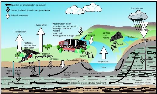
We can also see in the above drawing that in urban environments not only is there less infiltration, the infiltrated water is of worse quality, but in addition to this there is probably more demand on the aquifer, as there are probably quite a few wells in comparison to other less urbanised locations.

source: http://www.waterencyclopedia.com/
 The result of this continuous exploitation of aquifers with inadequate recharging has produced as a consequence the rapid descent of these, that also degrade in quality, sometimes with higher levels of salinity.

In some places such as India, this happens at an alarming rate:
The groundwater table is Delhi has depleted to 20 –30 metres in various areas across the city. Compared to a level of 30 – 40 feet at the time of Independence, the water table has dropped to 350 feet at certain places. It is said to be falling at 10 feet per year on an average. Groundwater levels have depleted by 2 – 6m in Alipur and Kanjhwla blocks, 10m ins the Najafgarh block, and about 20 m in Mehrauli block.
source: http://www.rainwaterharvesting.org/index_files/about_delhi.htm
Some are even more dramatic in their statements, an article from the Harvard Business School Alumni Bulletin states:
"groundwater supplies in Delhi are expected to run dry by 2015"
source: http://hbswk.hbs.edu/archive/5049.html

Another aspect of concern is called seawater intrusion, this happens in more coastal areas. Significant studies have been conducted into this phenomenon:

Seawater intrusion in coastal aquifers by Food and Agriculture Organization of the United Nations. Land and Water Development Division
In relation to aquifer contamination an interesting paper is An Overview of the Current Research on Remediation of Soils and Aquifers Contaminated by Organic Compounds by C.D. Johnston and G.B. Davis.

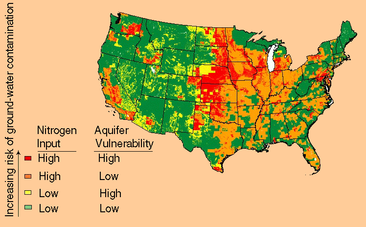
In the figure below we can see that groundwater contamination is not something to be dealt lightly with, in fact the situation that the areas that are most vulnerable are agricultural areas indicate a very noxious cycle. 
source: http://water.usgs.gov

So what is the solution? There are various, but from a consumer point of view it something that is not that complicated. In the diagram below is a simple representation of how a combined rainwater harvesting and overflow infiltration system is configured. The combination of underground tanks used to store water for immediate reuse, as well as to allow a separate tank for infiltration, that at the same time purifies the water, that is maintenance free, that requires minimum amount of power to pump the water for reuse as is practically just below the surface. Pumps for elevating and pumping ground water must be much more powerful, are as a consequence much more expensive, and in areas with rapidly descending water tables, this becomes a costly element if one has to the change the pump every few years to cope with the lowering water table.
Above we can see that with modular tanks, there is design flexibility, in relation to the amount of storage capacity for immediate reuse, as well as the infiltration tank. This way a project can harvest as much water as is necessary, conserve it ideal conditions. Water that exceeds the capacity of the tank for immediate reuse goes into the infiltration tank, and does so at an exceptional quality, and can go safely back into the aquifer.

Tuesday, March 1, 2011

How capillarity contributes to maintenance free systems

or Why do geosynthetics correctly installed permanently avoid clogging 

A frequent question I receive is related to the underground systems for water storage and management we work with, that have an envelope of geotextile, is: how is it that, the geotextile does not get clogged with silts and fines? It is an interesting question and though the easiest thing to say would be to explain that the system have been successfully used since 1986, and even before, without observations.


However, saying this sometimes is not enough, in this industry one works with a lot of engineers, and myself being an engineer, we want to know why and not only that, but have proof of it.

Though one could say that the existence of ad-hoc geotextiles have existed maybe since the first textiles where developed, our earliest human ancestors, normally used textiles to clothe themselves, or to use as vessels for carrying water or other substances. It would have probably been many years before textiles would have been available in larger enough quantities to use them for other purposes other than for essential personal use.

The interesting thing though is that I came to write about this topic, because of another reason that has nothing to do with textiles or tanks, but rather a personal hobby I have. This hobby, that I very much enjoy, is home brewing my beer. I am subscribed to Hombrewer magazine and in the Autumn 2011 edition, page 22, they had an article on particle settlement, that has precisely to do with this topic. The article titled "Clarification of Beer" explains how to determine the velocity of descent of particles in suspension, their terminal velocity and finally with this and having a distance of settlement, the time for settlement. The basic components of this system then is represented by this diagram below:
Where:
Fd = Force of drag
Fb = Force of bouyancy
Fg = Force of gravity

I found this representation quite interesting and the following formula is used in the calculations.
Where:
v = settling velocity (m/s)
g = acceleration due to gravity (9.8 m/s2)
ρ = density of water
ρs = density of particle
V = volume of particle
Cd = drag coefficient
A = projected area in the direction of motion (m2)

However it makes reference to a particle or solid in suspension that is not subject to the force of capillary action.

Capillary action is present in soil, as the spaces between granules act as capillary tubes. As such we can conclude that a more appropriate model for fine particles should change to consider this. Saying this, though we could make and endless regression where we could consider every particle in a soil profile to be under this influence, and it is... to an extent, however the difference in behaviour therefore lies in the particle densities and volumes that where mentioned above. This comparative differences are what would define "free" particles or that are in suspension, as particles that are freer to move in the soil media. The important aspect that we should consider is that this modelling is relevant for particles in suspension. As such, for example in the typical installation that we deal with, where sand is utilized, the sand is not in suspension, hence limiting the "endless" regression.

Taking the previous into account we can update our model and diagram to include the following, we can add another vector, Fc, Capillary Force, to the model as represented below.
Where:
Fc = Force of capillarity

However there is more to this than just including the concept of capillarity. Capillarity not only acts because of water cohesive force, that is manifested in waters surface tension, but also through water's adhesive force. We must remember that the difference between cohesion, that is the force of same molecules attracting to each other, and adhesion, the force of different molecules attracting to each other. As such, for our purposes, that particles should be uptaken against the force of gravity is also dependant that the suspended particle should not adhere to the particles not in suspension.

If we analyse these forces then, we can take the liberty and a assume a value of the  force of drag as negligible and the force of buoyancy as that which allows the smaller particles to be free or in suspension, but for our effects, do not enter into our equations either.

We need to then determine the force pushing upwards, that will take the particle in suspension in the same direction:
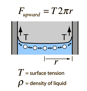
source: http://hyperphysics.phy-astr.gsu.edu/hbase/surten2.html#c6
Values of surface tension can be obtained from the table below, being it interesting to note the influence on temperature, we had seen in a recent post on my blog the effect that depth positively has on the water quality, here we see it again.

Effect of temperature in degC on surface tension of water in units of mJ m-2 or mN m-1(Kaye and Laby, 1973)

Temperature010203040
Surface tension75.774.272.7571.269.6

The upwards force has to overcome the force of gravitation on the particle, which can be expressed in this way in terms of finding the point of equilibrium:

Fg = mg
We can then say:
mg = T2πr

As we want to obtain the value of r, we arrange the variable in the following way:

r = mg/T2π

As we have the value of surface tension, we need to find the mass for a "typical" particle of silt.

Specific gravity is the ratio of the weight in air of a given volume of a material at a standard temperature to the weight in air of an equal volume of distilled water at the same stated temperature.

In natural soils, particle specific gravity will usually “range numerically from 2.60 to 2.80. Within this range, the lower values for specific gravity are typical of the coarser soils, while higher values are typical of the fine-grained soil types. Values of the specific gravity outside the range of values given may occasionally be encountered in soils derived from parent materials which contained either unusually light or unusually heavy minerals.” [Ritter and Paquette 1960, p 182]

To use a worst case scenario of sediments or fines with the highest specific gravity we can consider clay or silty clay that can have specific gravities of up to 2.9, this is also heavier than quartz that has a specific gravity of 2.65, in fact most of sand is made of quartz, and as it is the media recommend for providing the capillarity and is not in suspension, we could also presume that the particles in suspension have a lower specific gravity than quartz sand.

In this case a consider what would a silt particle similar to a small sand sand grain we can assume the following, a diameter of 0.060 mm, that implies a volume of 2.51e-10 m3, and a specific gravity of 2.65 for mineral quartz, this gives a value of 0.67 mg.

If we replace the value in the equation we obtain the following:

r = (6.7e-7 * 9.8) / (72.75e-3 * 2 * 3.14)

Which provides us with the result:

 r = 14.4 μm

This can be expressed as a diameter which in the case will be 28.8 μm, which will serve a reference for pore sizes. This pore size is practically on the border of what has been defined as Mesopore and Micropores 1.

This then is the size of the capillary that provide equilibrium so that a particle smaller than the size of a grain of sand to remain in suspension. The capillary radius depends on the the particle size of the media and it has been classified in the following manner.
source:http://upload.wikimedia.org/wikipedia/commons/6/65/SoilTextureTriangle.jpg
Pore sizes for soils can be calculated with the following table:

Soil Texture


Bulk Density (g/cm3)


Porosity (%)


Available Soil Water (inches/foot of soil depth)


Range


Average
Coarse
  Sand


1.65


38


0.5-0.8


0.7
  Fine Sand


1.60


40


0.6-1.0


0.8
  Loamy Sand


1.60


40


0.7-1.1


0.9
  Gravel/Cobble in Coarse Texture


0.6-0.8


0.7
Moderately Coarse
  Loamy Fine Sand


1.55


42


1.0-1.3


1.2
  Sandy Loam


1.50


43


1.2-1.6


1.4
  Fine Sandy Loam


1.50


43


1.2-1.7


1.5
Medium
  Gravel/Cobble in Medium Texture


1.1-1.3


1.2
  Very Fine Sandy Loam


1.45


45


1.6-2.2


1.9
  Loam


1.40


47


1.6-2.3


2.0
Moderately Fine
  Sandy Clay Loam


1.35


49


1.7-2.4


2.1
  Silt Loam


1.35


49


1.8-2.5


2.2
  Clay Loam


1.35


49


1.8-2.5


2.2
Fine
  Sandy Clay


1.30


51


1.9-2.5


2.3
  Silty Clay


1.25


53


1.9-2.5


2.3
  Clay


1.20


55


2.0-2.5


2.3
Peats and Mucks


2.0-3.0


2.5
source: http://cru.cahe.wsu.edu/CEPublications/pnw0475/pnw0475OP.html

A ratio is obtained by dividing  of porosity percentage with its complement, for example: in clay loam the pore space (49%) makes up almost the same amount of volume as the volume of soil particles (51%); multiply the ratio 49/51 times the 0.063 mm particle diameter to get the average pore size of 0.061 mm.

It is now interesting to see what are typical average pore sizes for soils, for example sandy loam 90μm, clay loam 61μm 2.

As the height of a capillary depends on the weight of the column of water, this is directly related to the radius of the capillary, as such the smaller the diameter of the capillary the higher the the column of water. This then produces a dichotomy in terms of that the smaller the particle size gets, eventually you get to clay sized particles that do not have much infiltration capacity and do not behave in a manner that provides capillary action.

From the above then we could conclude that the pore size we see in sandy loam, 90μm, for example is too small to provide the capillary action that we require of 28.8 μm, that we have previously determined as what would provide a capillary force that would overcome the force of gravity that the suspended particle is subject to. The situation is though that the sand, or for that case practically any soil media, is irregular and provides pore sizes that very often are much smaller that the average 90μm we calculated, as well as it providing spaces that are also larger. To illustrate this we can see the diagram below.


source: plantandsoil.unl.edu/
In another example we can see that even more variability can be represented:
source:http://www.earthdrx.org/cap11.jpg
Precautions necessary

In the industry we often hear of situation where supposed permeable systems become impermeable and that then need backwashing, with "sophisticated" technologies. Wouldn't it be more sophisticated to have systems that does not need maintenance or a costly backwashing system, that would not be required in the first place, if the application was designed correctly? There are many examples of these, if we were to analyse these in more details we could observe that source or cause of the clogging resides in both what we have described above, as well as other elements, that will probably include biological activity.

There are examples of these that come to mind, however to delve into them would be an odious practice.
Conclusions

Having analysed all of the above information what can be concluded is that if underground water management systems are installed correctly, with a suitable layer of soil media that provide capillarity, experience has shown that geotextiles do not clog.

This is possible due to the fact that it is possible to infer that there are spaces where capillary radii are smaller than those required to provide enough force to overcome gravity, that it in fact acts, literally, as a micro physical mechanism that provides a cleaning action that maintains the geotextile clean and free of clogging.

References:

Soil analysis: an interpretation manual By Kenneth Ian Peverill, L. A. Sparrow, Douglas J. Reuter, 96
http://www.newton.dep.anl.gov/askasci/env99/env201.htm
http://140.194.76.129/publications/eng-manuals/em1110-2-4000/c-7.pdf
http://gozips.uakron.edu/~mcbelch/documents/SpecificGravityofSoils.ppt
http://wwwrcamnl.wr.usgs.gov/uzf/abs_pubs/papers/nimmo.04.encyc.por.ese.pdf
T.J. Marshall, J.W. Holmes, and C.W. Rose (1996), Soil Physics, 3rd Edition, 42-45